Cloned Gate Opener
2017Back in 2017, I had just moved into a new gated complex with 3 other housemates; unfortunately, our landlord only provided 2 gate openers, and the HOA charged $100 for each additional remote. I thought this would be a good opportunity to see if I could clone the remote for a bit cheaper. Some resources I found that were particularly useful:
- http://samy.pl/dingdong/
- http://mightydevices.com/?p=300
- https://wiki.cuvoodoo.info/doku.php?id=megacode
I eventually also discovered that someone does sell a premade cloner for this particular remote model ($25), but that was after I had finished this project (and buying this would have been less fun).
Initial Investigation
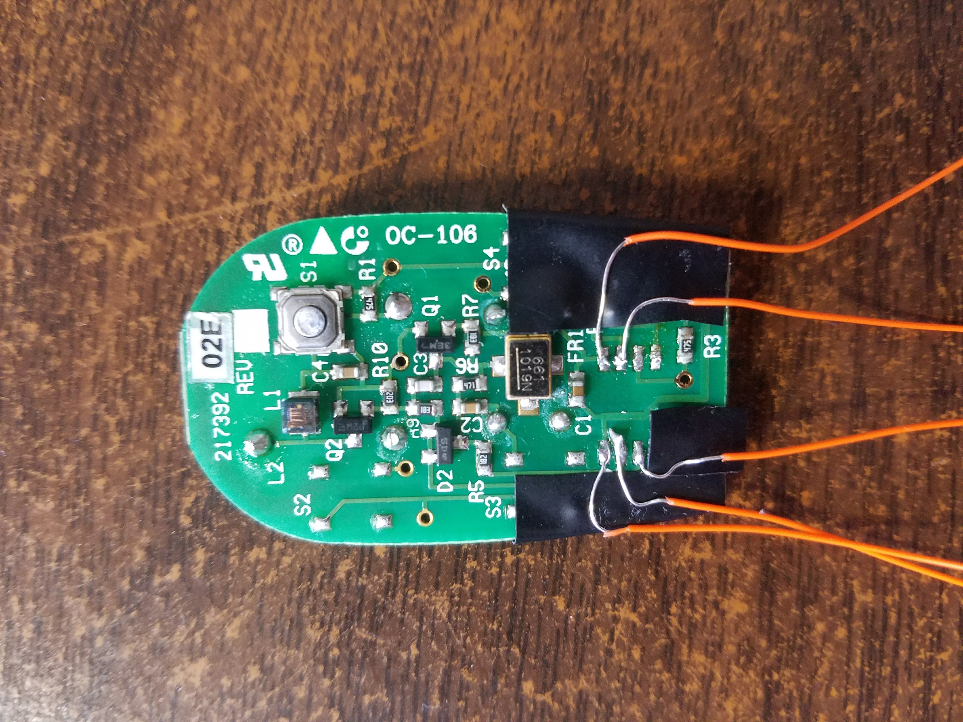
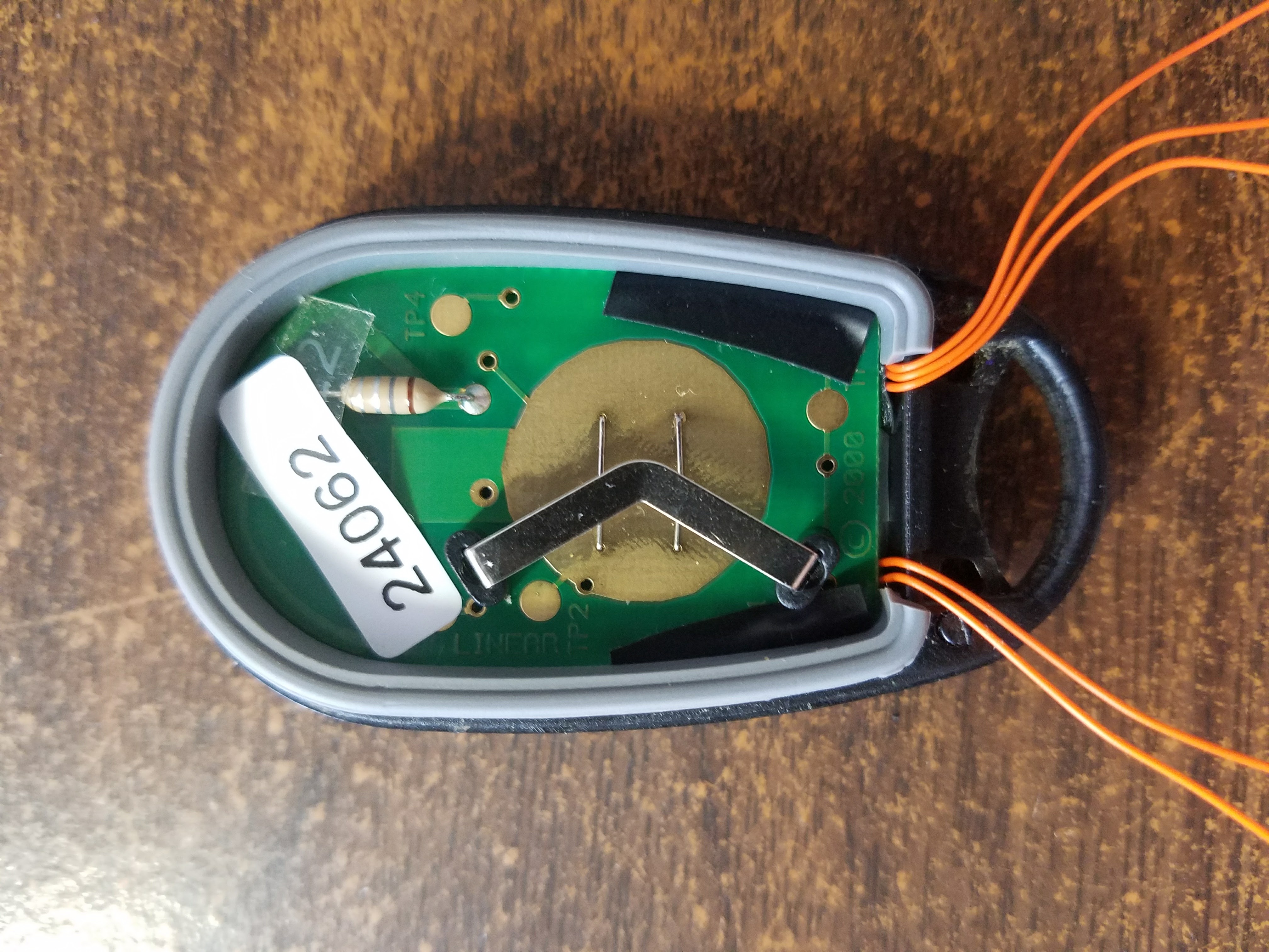
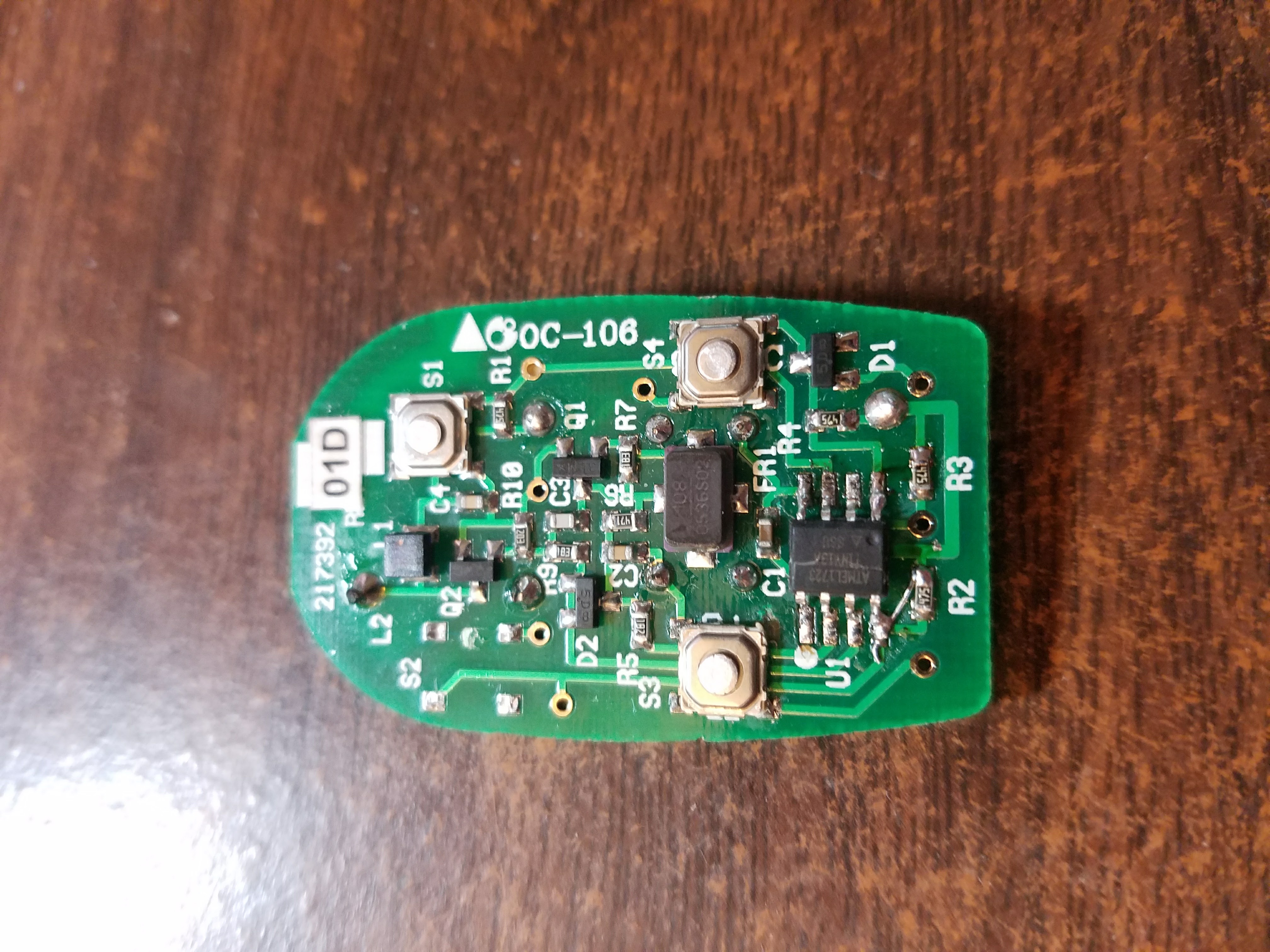
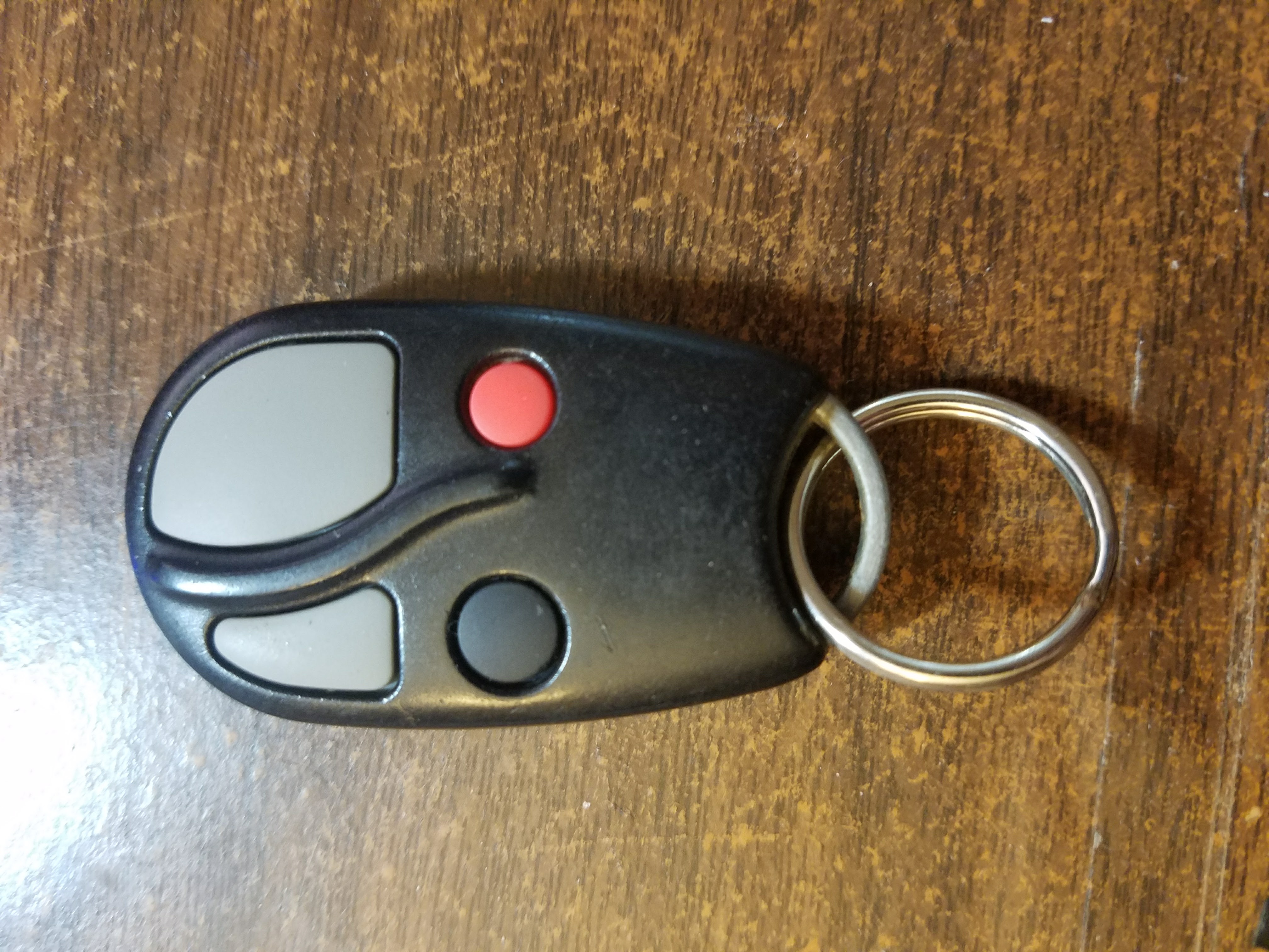
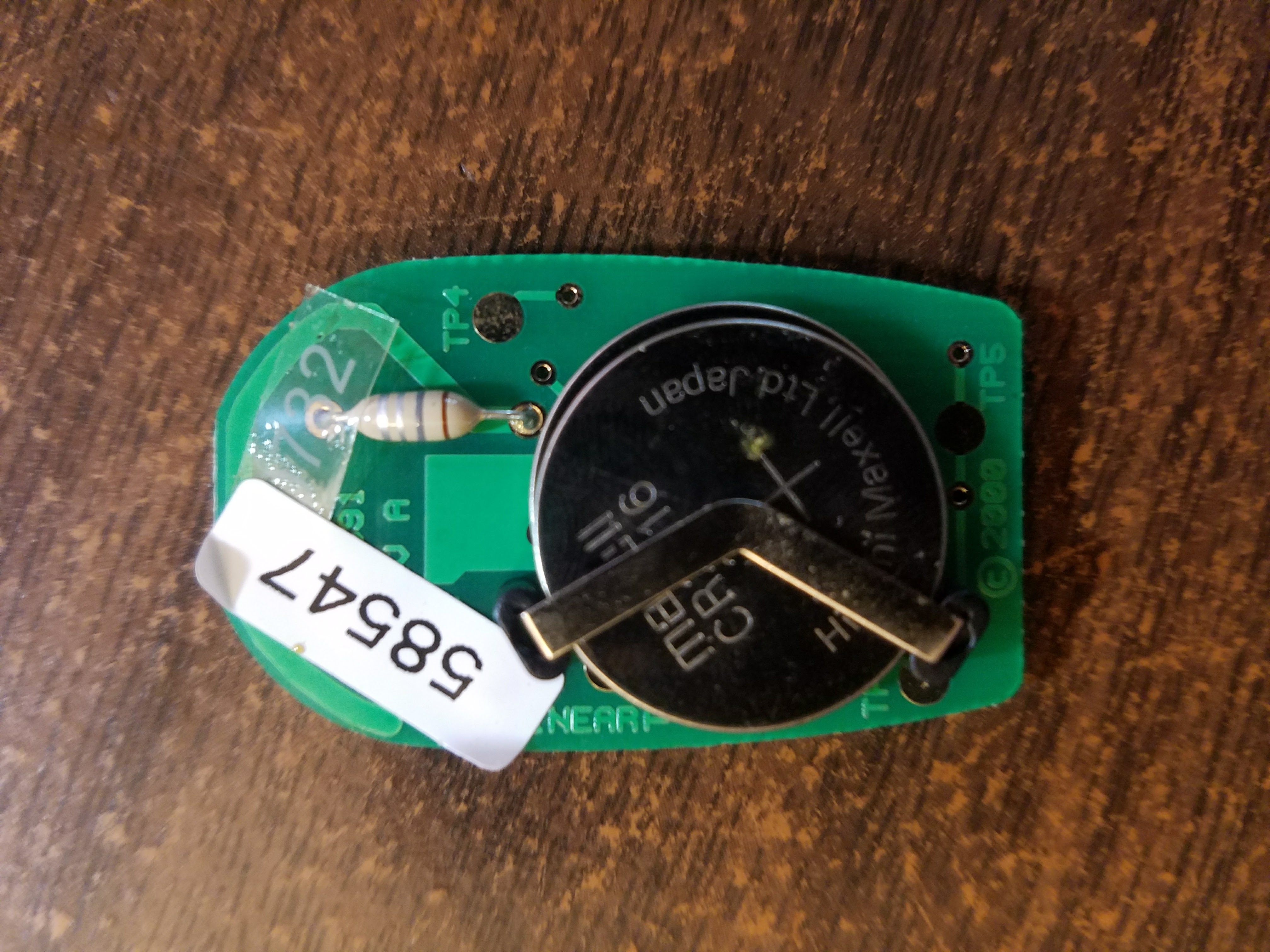
The first step was to open a remote up, since the outside didn’t have any distinguishing marks.
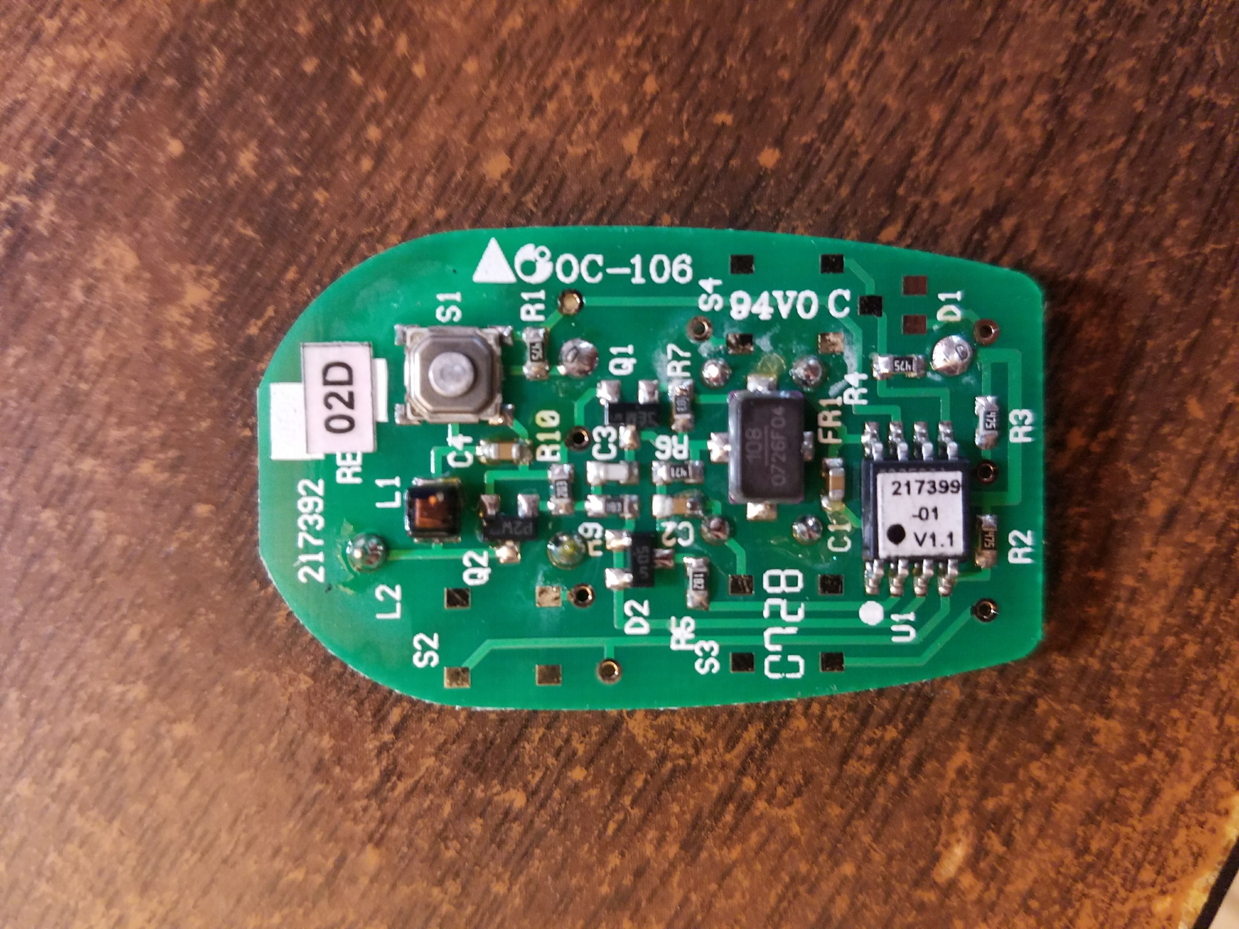
No dip switch for setting a code and no FCC ID. However, I did find the manufacturer’s name (Linear), and some searching got me to the ACT-31B product page, which explained that each remote was factory programmed with a unique code, and that the receiver needed to be programmed to accept individual remotes.
Additional searching got me the FCC ID EF4 ACP00872, and I was able to look up the device in the FCC database, which provided a ton of information. I found that the device transmits at 318 MHz and uses OOK modulation of the carrier wave and a kind of PPM for the data encoding. In addition, there was a block diagram, functional description, and even the entire schematic.
Extracting the Code
Since I had a working remote and knew the schematic, I could have just used an oscilloscope to probe the signal pin for the code. Unfortunately, I didn’t have a scope at the time, so I went for a more indirect approach - an RTL-SDR. This let me extract the actual RF signal the remote transmits. Demodulated:

As we can see, there is an initial sync pulse, followed by 23 data pulses. Each pulse is 1 ms, with one in each 6 ms period. This translates to the code 01001110010010110100010, if we assume that a pulse in the earlier half of the period means a 0. Of course, whether it means 0 or 1 doesn’t matter, as long as we can reproduce the code.
Transmitting the Code
Because the remote uses 318 MHz instead of the more common frequency 315 MHz or 433 MHz, I couldn’t just use a transmitter like this. I briefly considered building a transmitter from scratch, but it would be a little risky since I didn’t have much analog experience. Eventually. I decided to just buy another remote from ebay (~$10) and hack it to transmit the same code.
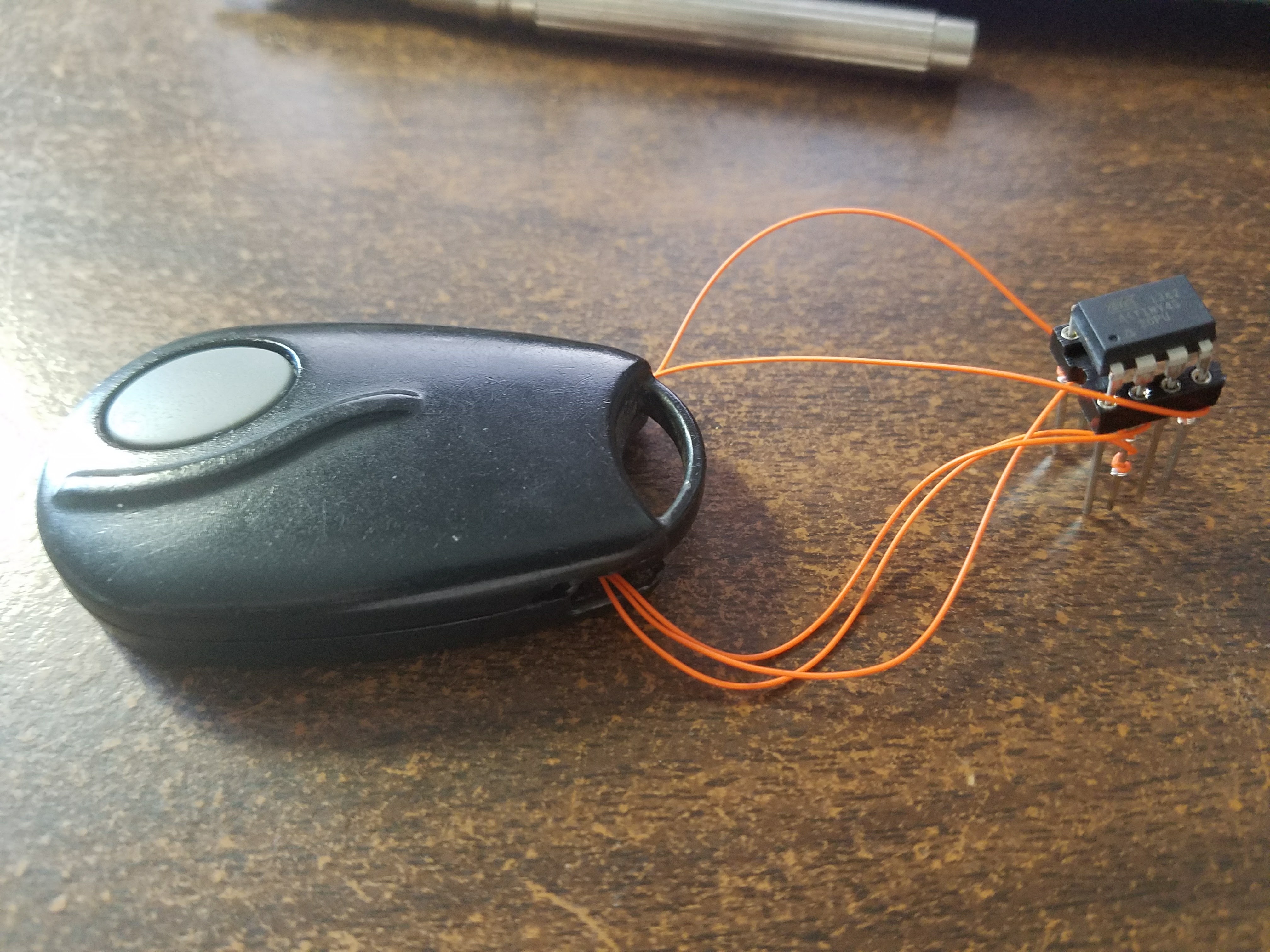
I desoldered the existing PIC microcontroller and wired up an ATtiny45. The initial breadboard prototype in all its janky glory:
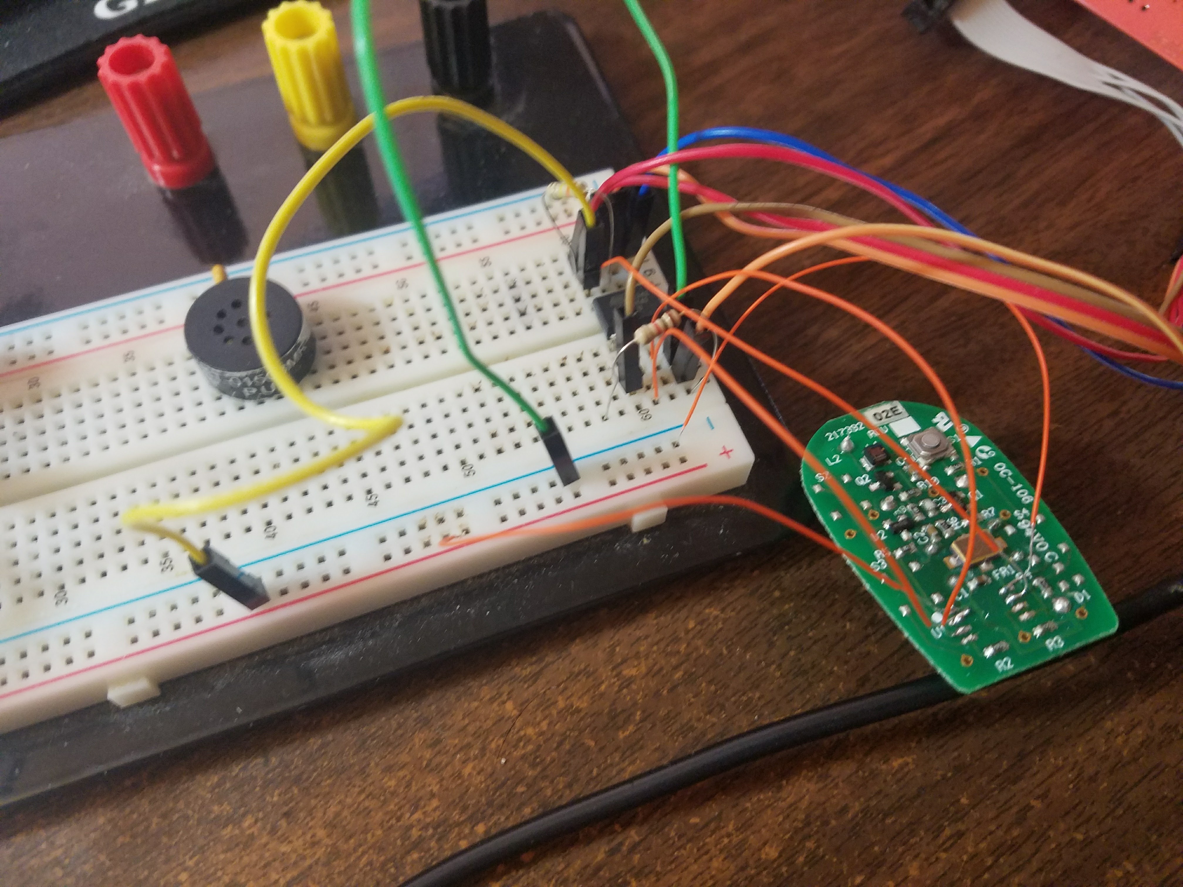
The software was pretty straightforward. Instead of messing with timers, I just used _delay_us() for simplicity. I fed the button input to INT0 and had the actual transmission in the external interrupt, so the ATtiny could stay in powered down mode until the button was pressed.
To debug / check my work, I used the RTL-SDR to look at the transmitted signal. One thing I did notice was that the ATtiny’s internal clock seemed slightly fast (roughly 137/135). I wasn’t sure if this would actually matter, but I corrected it by simply updating the F_CPU flag to 1014814 from 1000000. The final transmission:
 |
|---|
| Hacked remote signal |
|
| Original remote signal |
As you can see, the signals were essentially the same. Time to do the real test!
Testing in prod: At this point it was like 2 a.m., but I was too excited to wait. I put the breadboard into a box with my laptop as a power source, and walked to the gate for an official test. And (a little surprisingly), it worked!
Some Cleanup
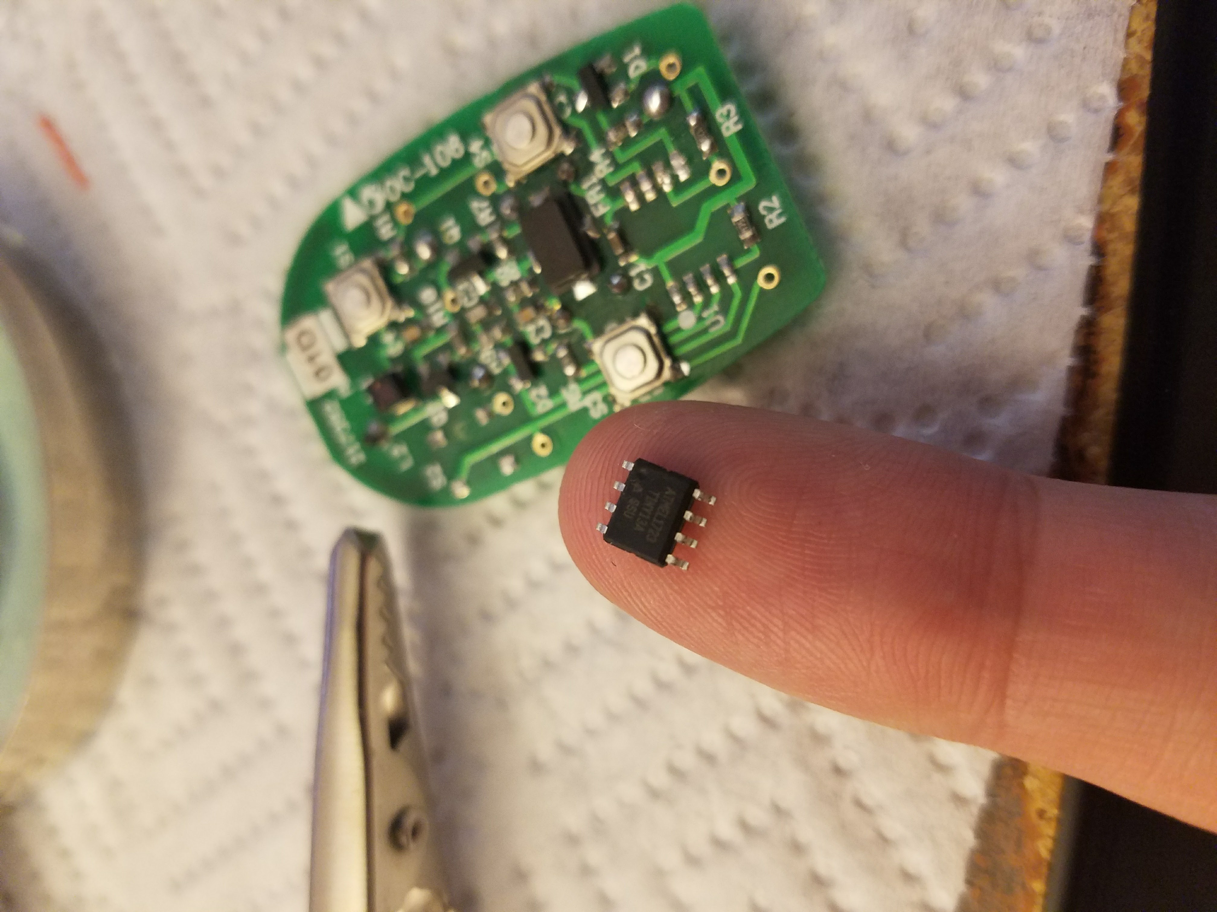
Finally, I moved the setup from the breadboard slightly more permanent setup. I taped up the pcb/wires with some electrical tape to avoid undesired contacts, cut some cutouts in the casing for the wires, and attached the ATtiny via a wirewrap socket. Not the most pretty solution, but I was working with the materials I currently had on hand. Eventually, I did get some SOIC-8 ATTiny chips, which let me fit the microcontroller directly inside the remote (had to flip the orientation to make the power pins match up, and had to change the above code snippet a bit).
There was a small issue in terms of the power source - the original remote ran off of two 3V batteries, which was just slightly above the rated 5.5V max of the ATtiny. Fortunately, a simple solution was to just use a single 3V battery; this worked fine and didn’t seem to noticeably impact the remote’s range.