Quadcopter Electronics
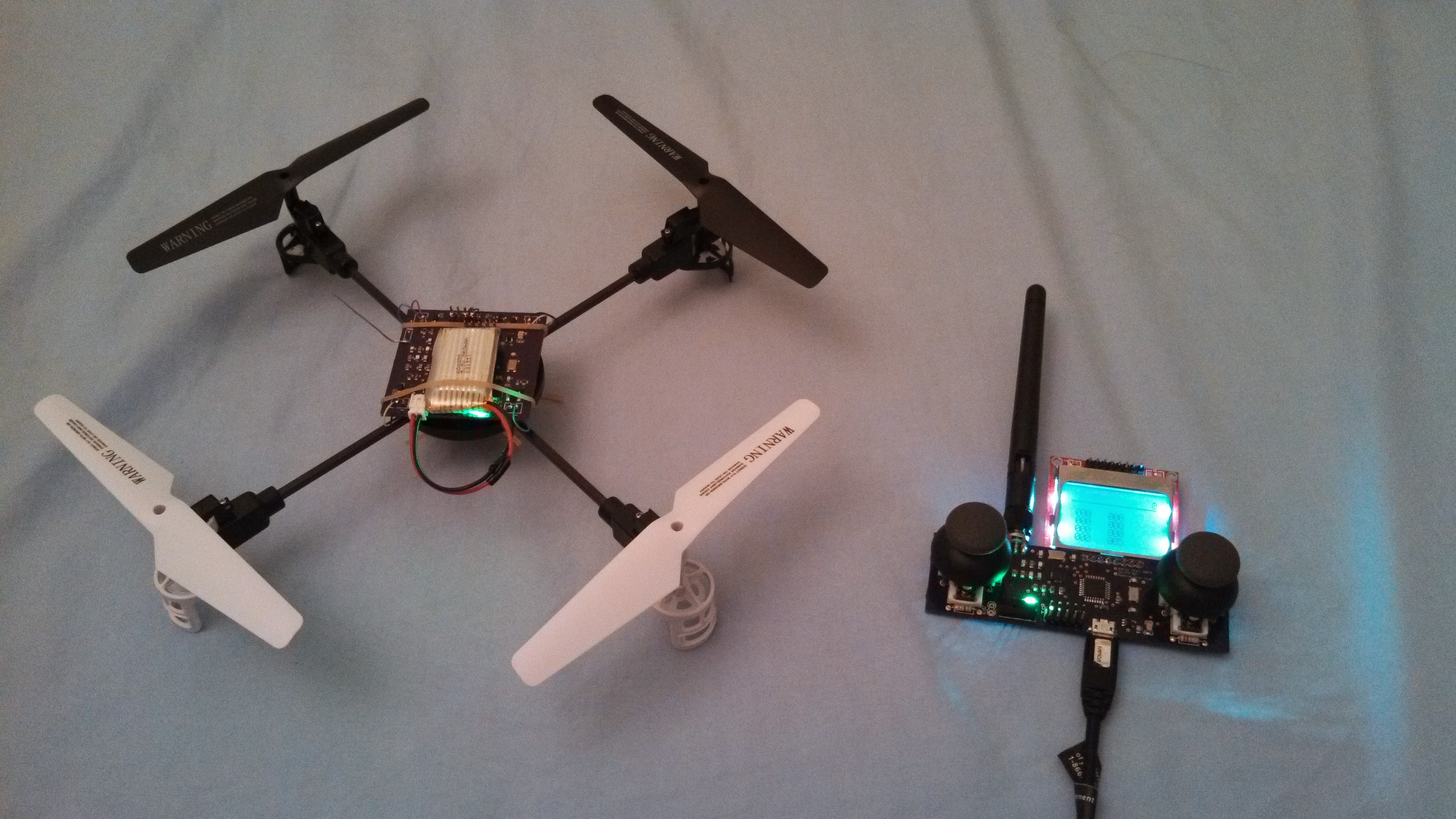
2014The EE/CS 52 course at Caltech is a project course students can take if they want to propose, design, and build their own embedded systems project independently over 10 weeks. For my project, I built the electronics for a small quadcopter from scratch. The system consists of a Flight Unit (flight controller) board mounted on the quadcopter, as well as a Remote Unit board for the remote transmitter. The frame and motors come from a Syma X1 toy quadcopter. While not the most stable, the quadcopter does actually fly, which I’m pretty happy with given the time constraints.
- Quadcopter balances itself using accelerometer and gyroscope data
- Analog control over the quadcopter’s throttle, pitch/roll angle, and yaw rate
- Tunable PID constants using the Remote Unit
- Graphical time series display of the pitch or roll angle on the Remote Unit
Hardware
The Flight Unit board is physically attached to the quadcopter and controls the motors. The Remote Unit board acts as the user interface unit and controls the quadcopter wirelessly. The Flight Unit and Remote Unit share some common components:
- ATmega328P MCU to run the main application code
- nRF24L01+ RF transceiver (SPI) to enable the units to communicate
- MIC5219 3.3V voltage regulator for either 1-cell LiPo or 5V usb supply
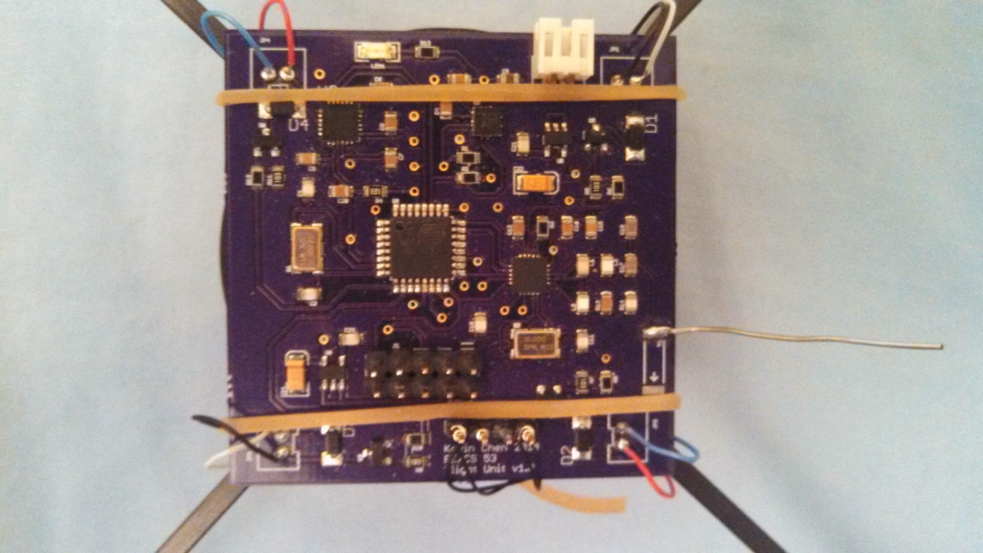
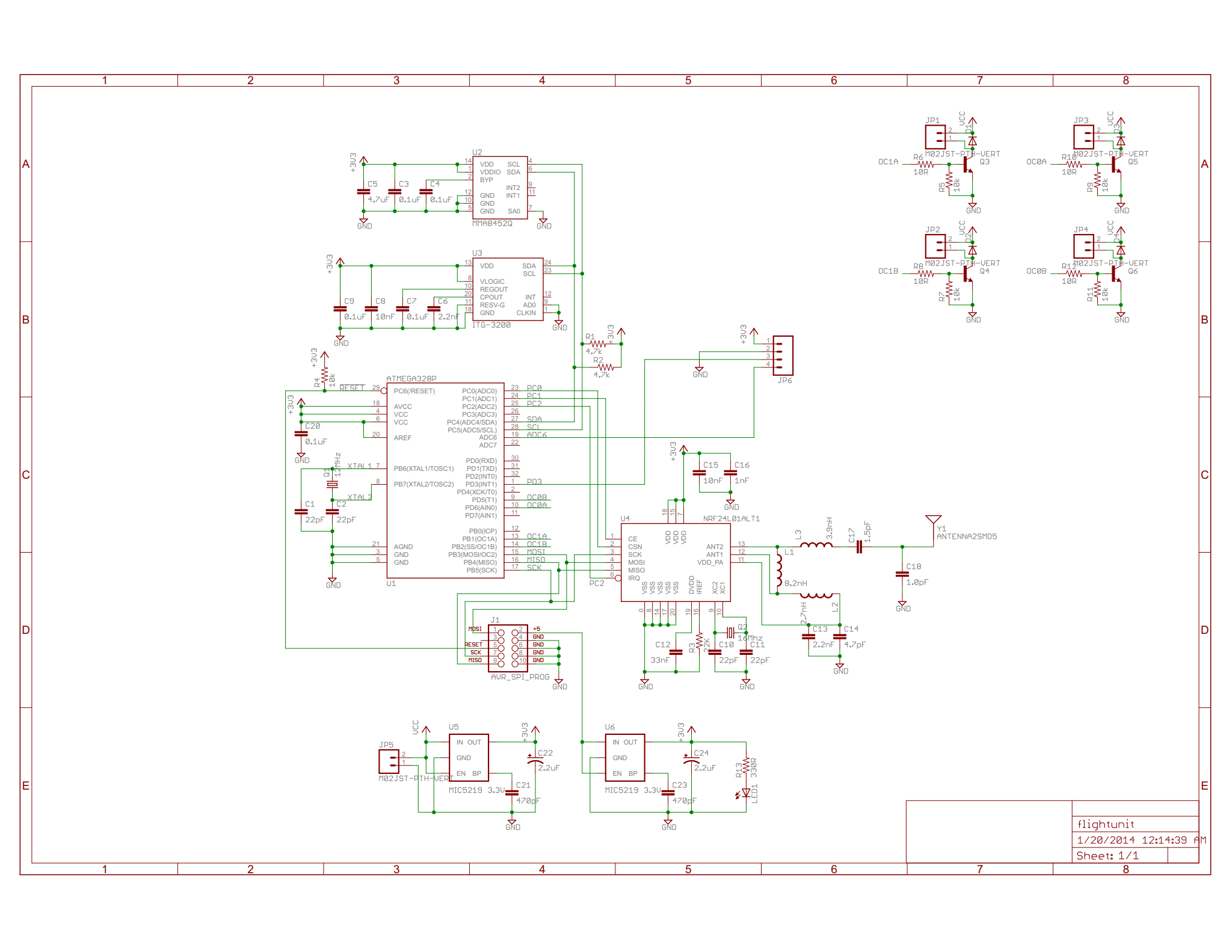
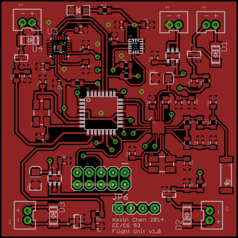
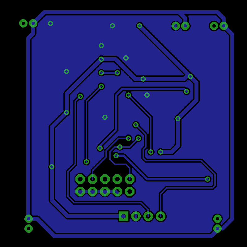
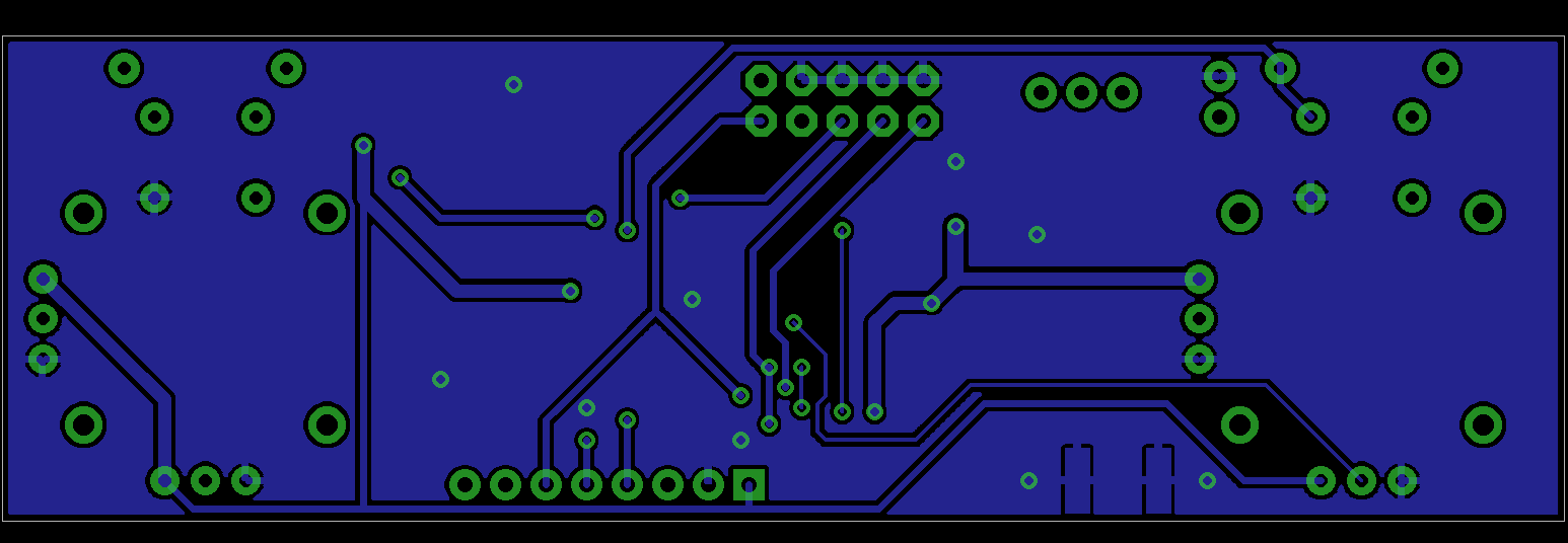
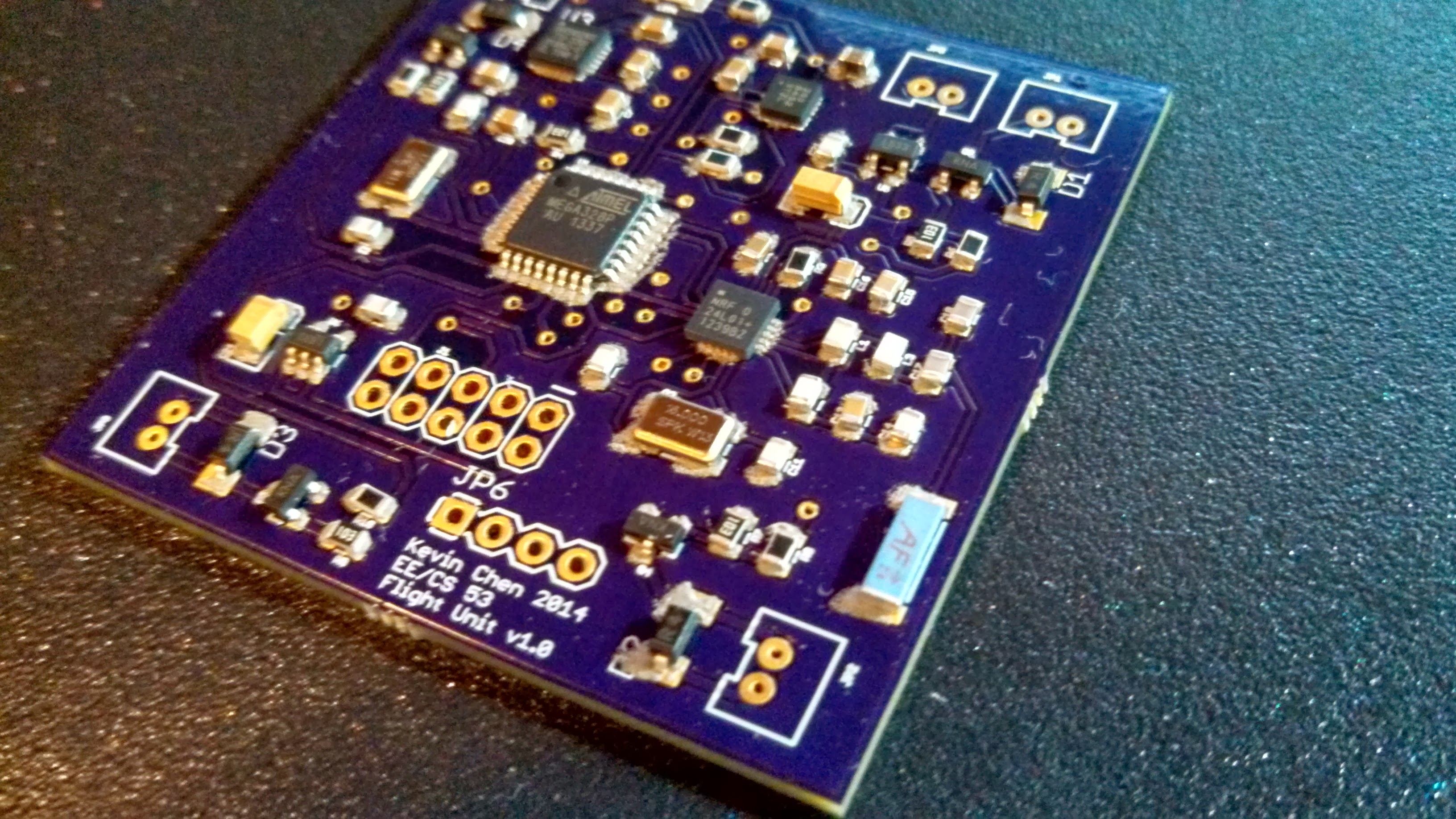
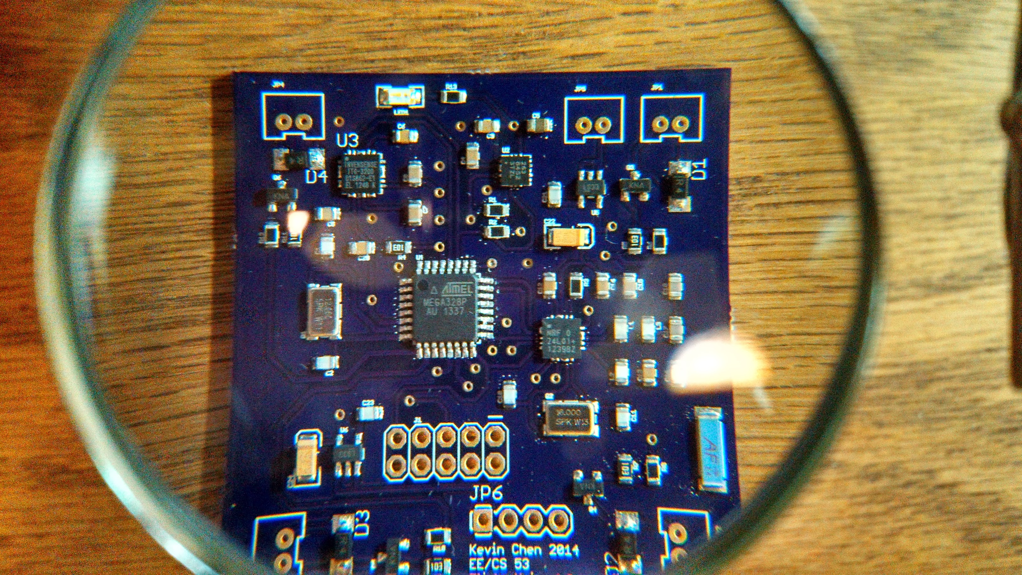
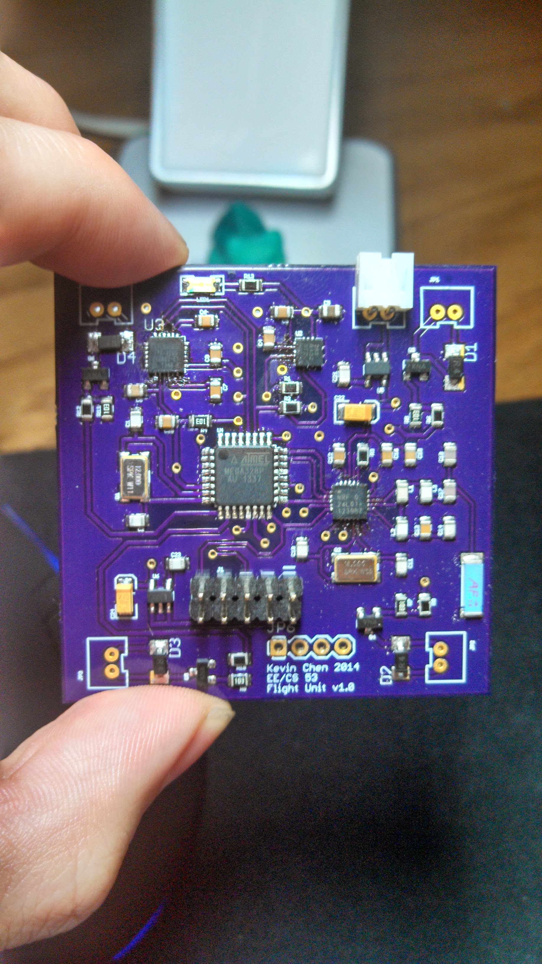
Flight Unit Schematic and PCB
The Flight Unit includes additional sensor and control components:
- MMA8452Q accelerometer (I2C)
- ITG-3200 gyroscope (I2C)
- ZXMN3F30FH N-channel MOSFETs to drive the motor
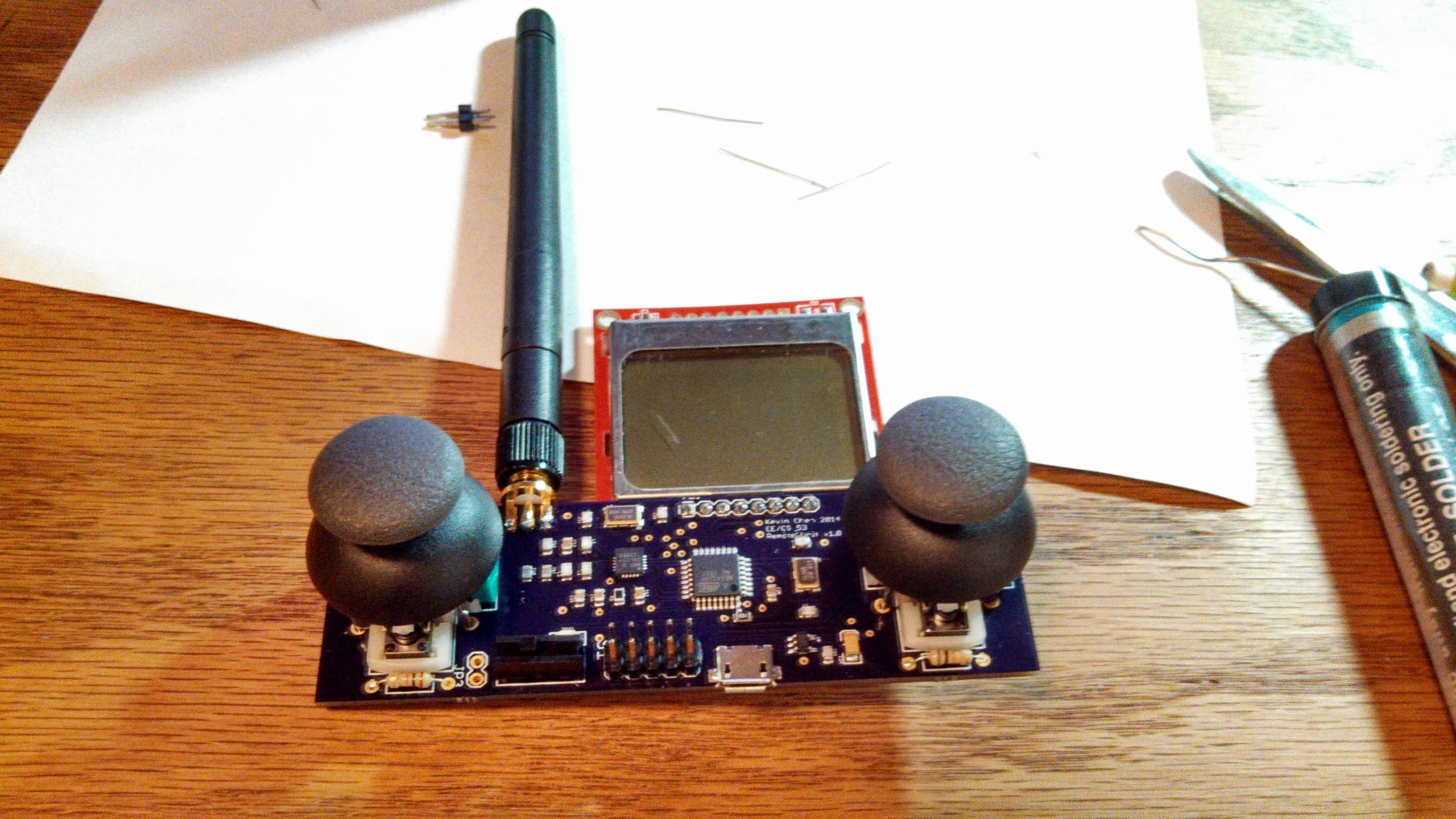
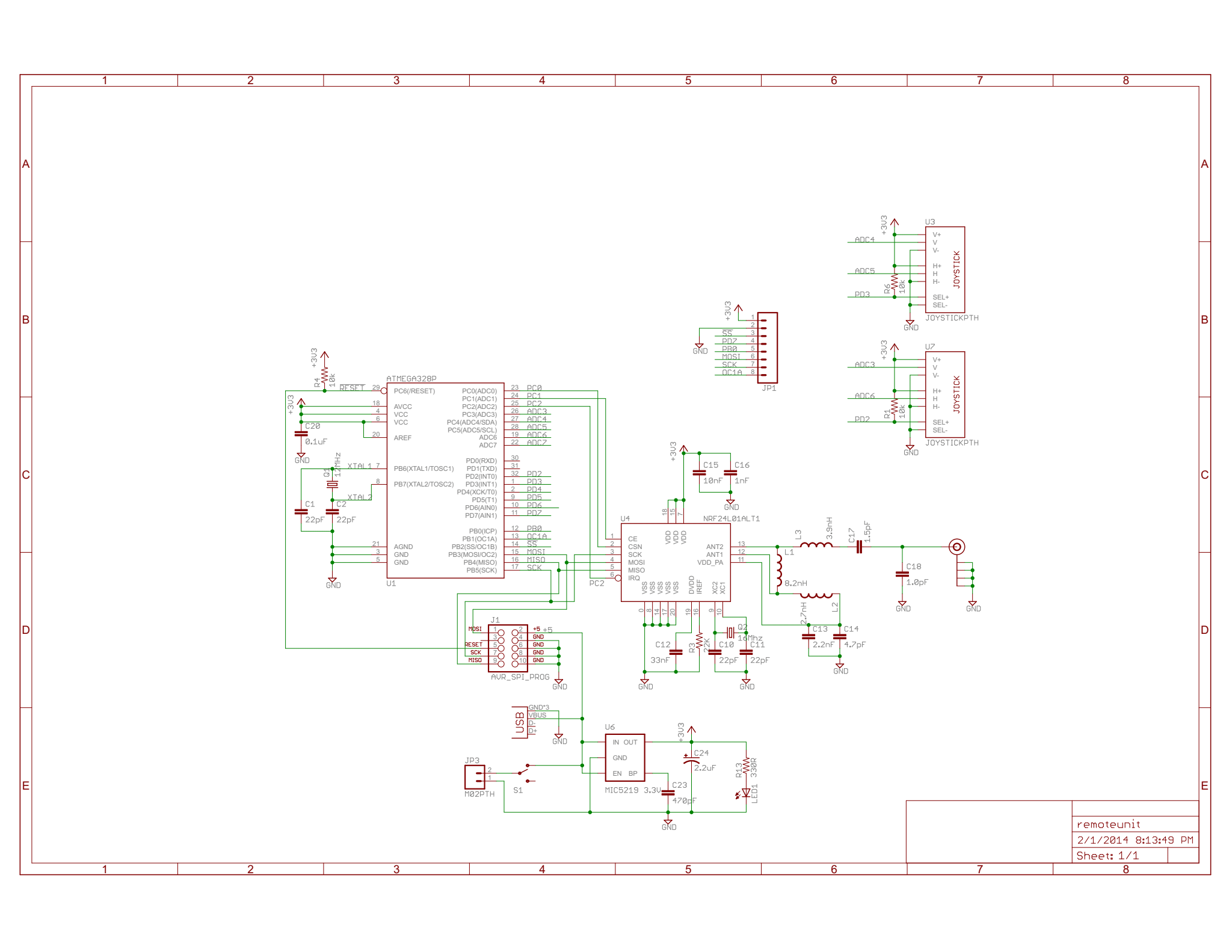
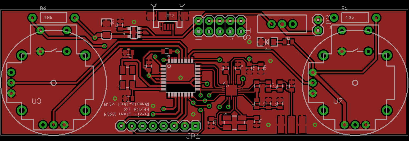
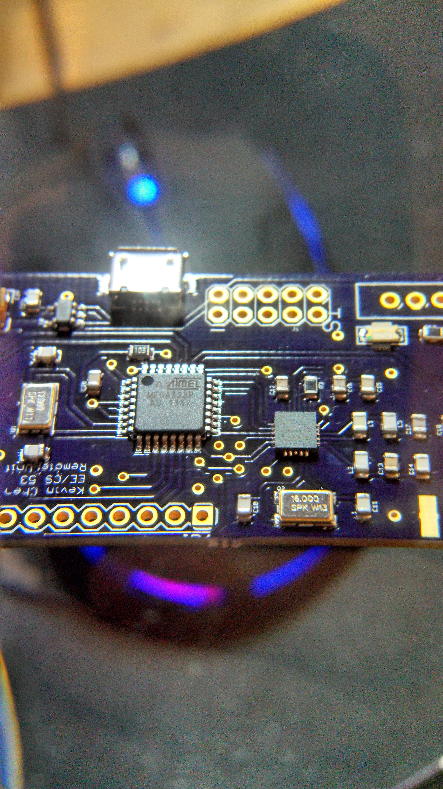
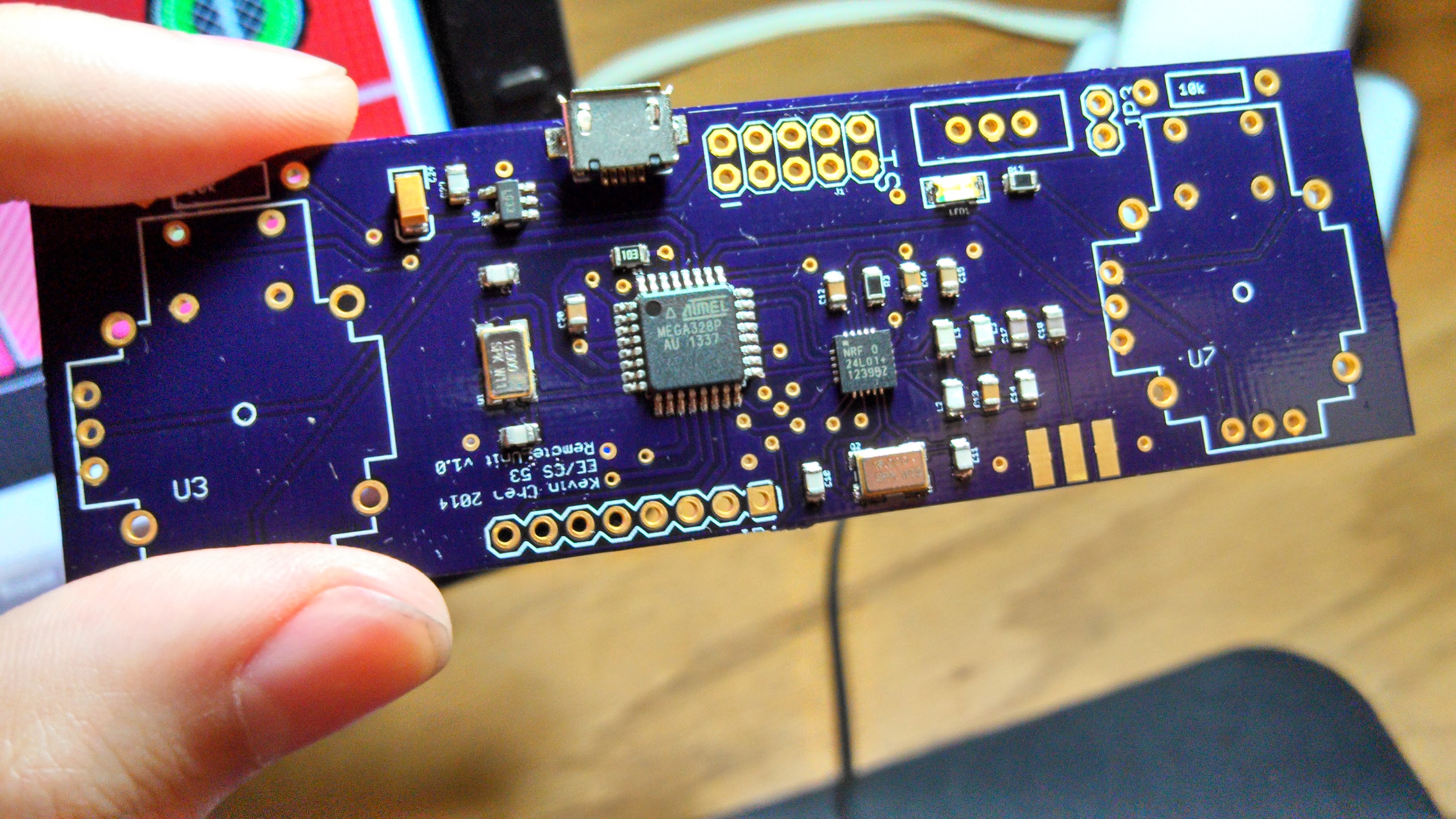
Remote Unit Schematic and PCB
The Remote Unit includes additional user interface components:
- Analog Joysticks (game controller style ones)
- Nokia 5110 LCD (SPI)
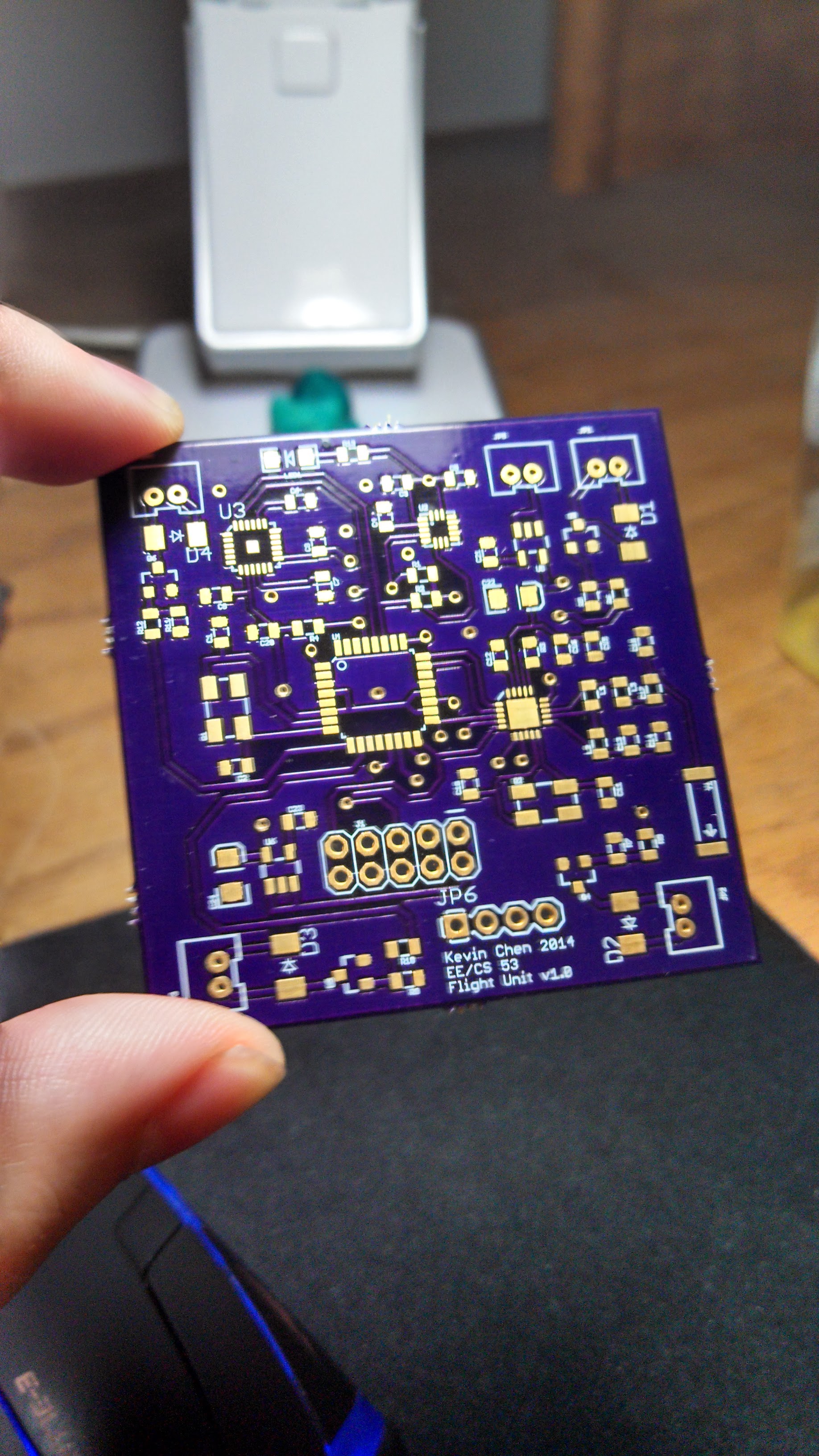
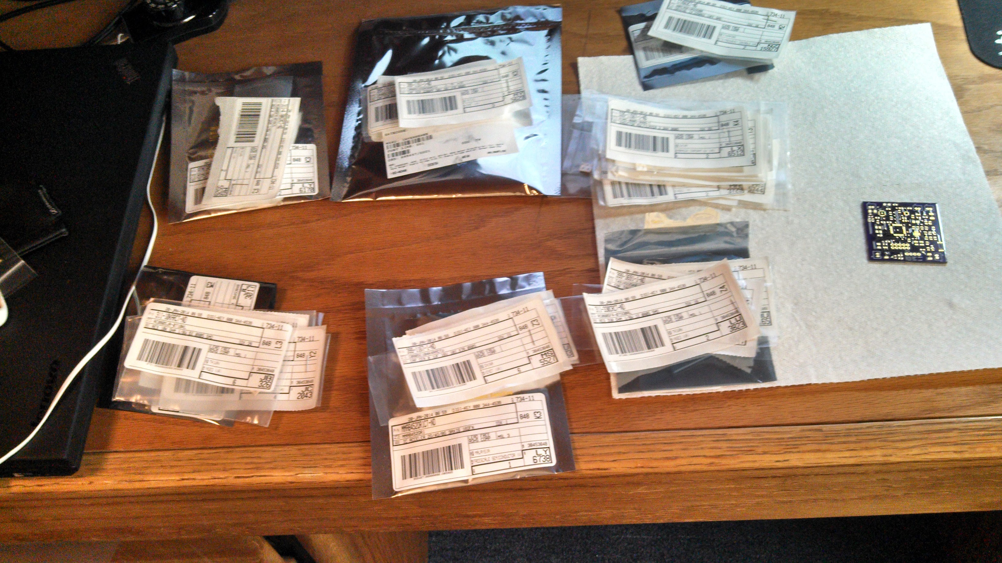
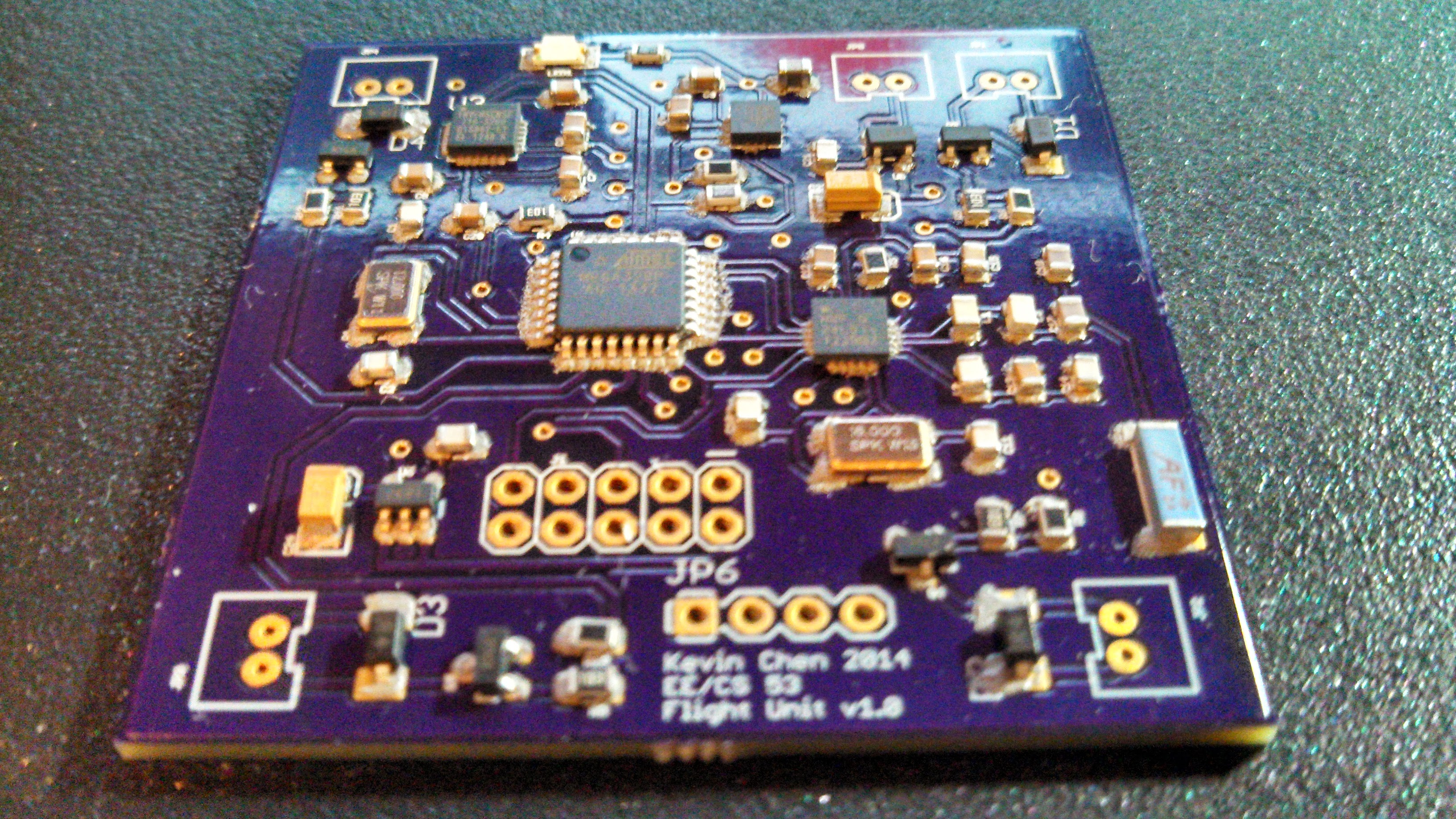
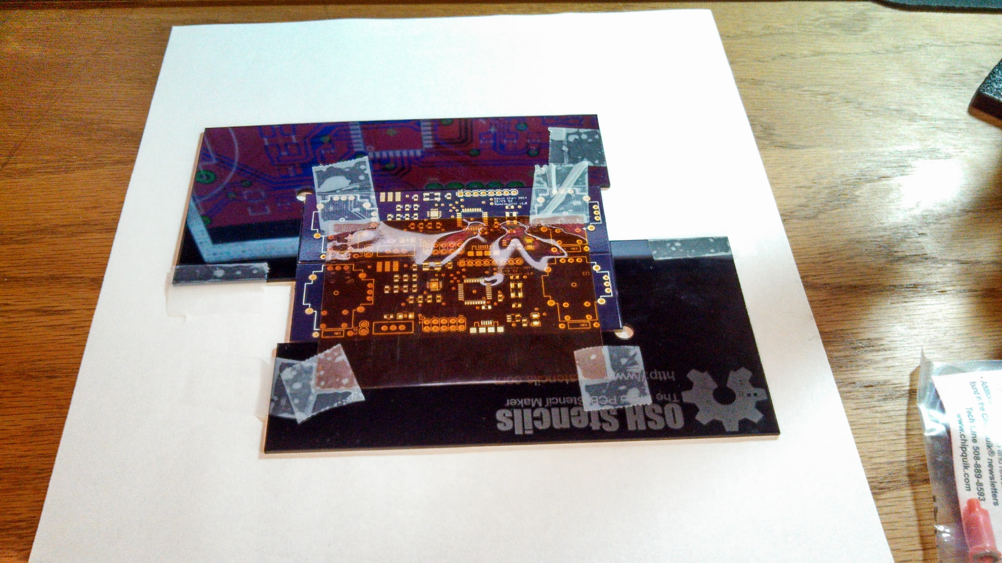
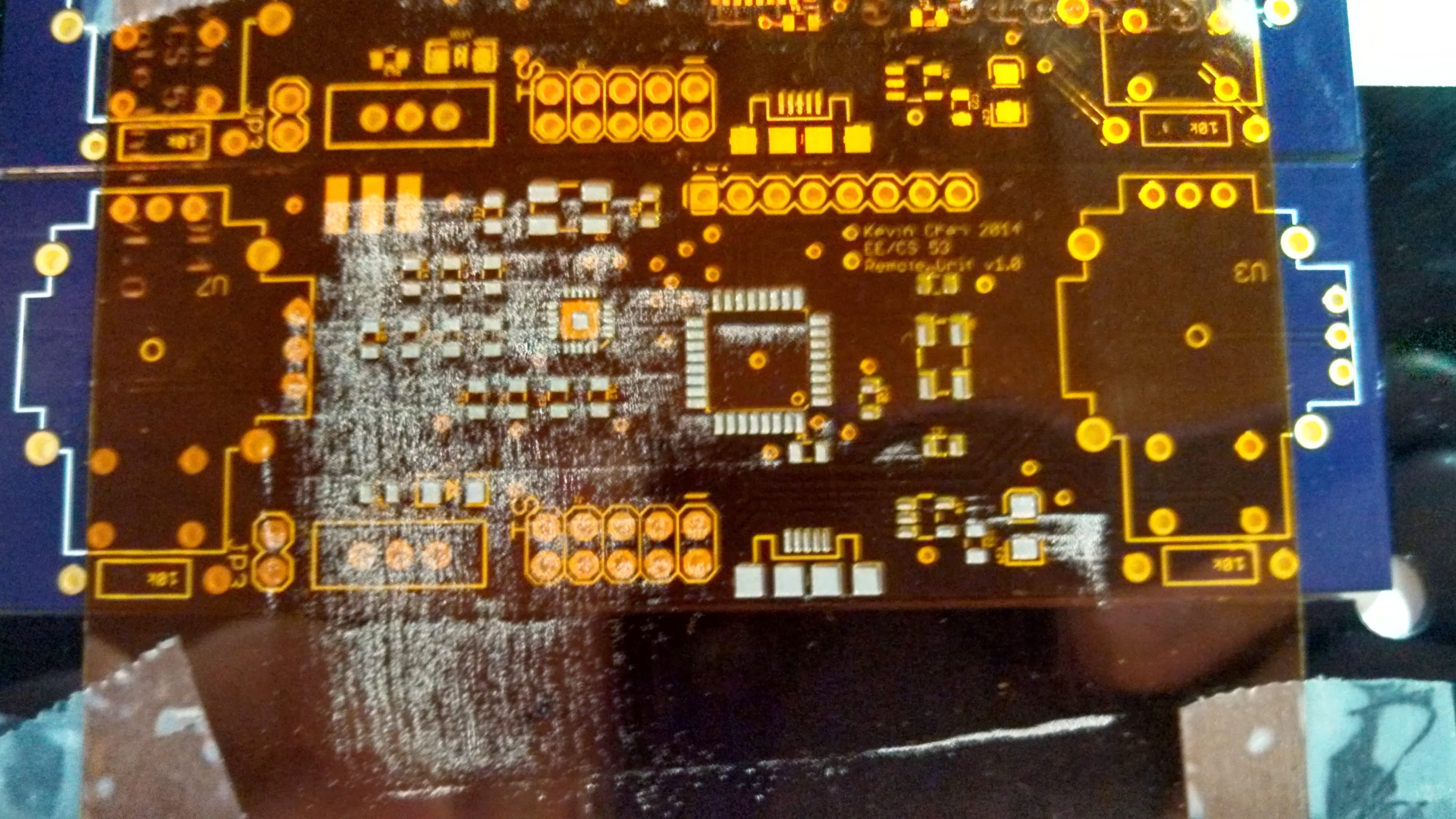
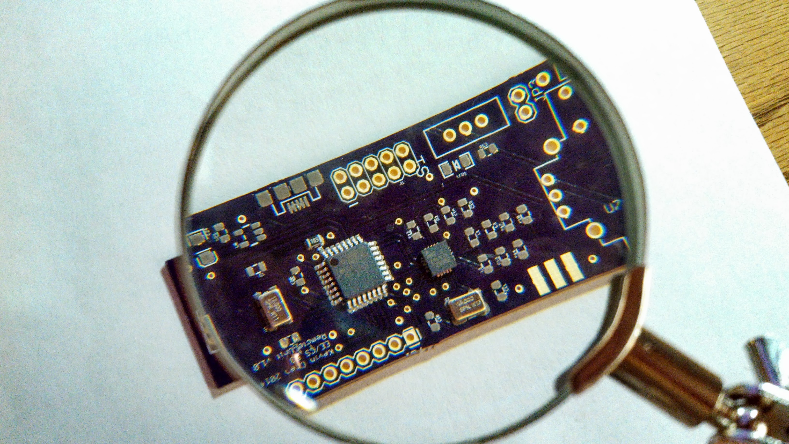
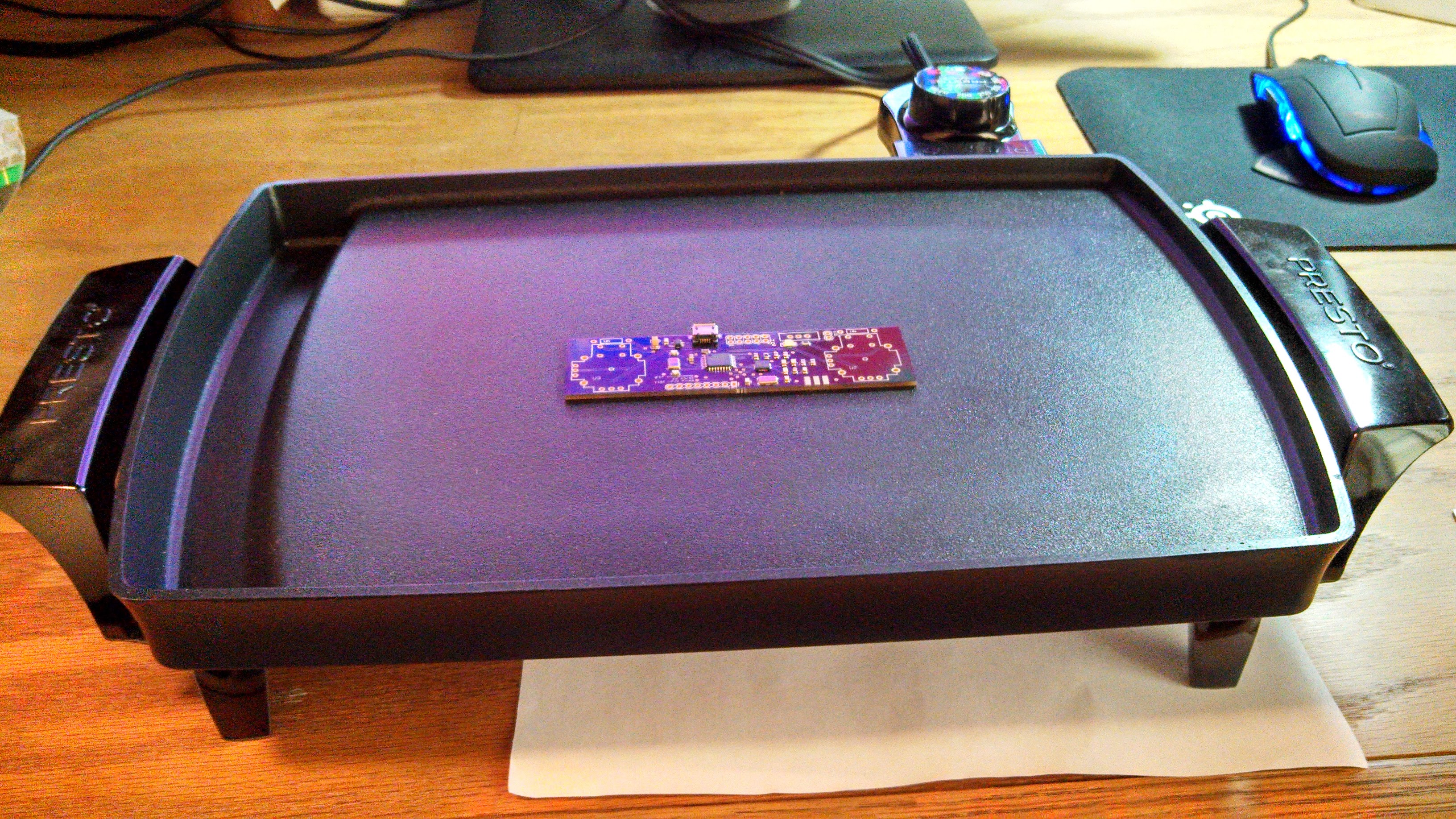
Construction Details
I ordered the PCBS from OSH Park and most other components from Digi-Key. This was my first time working with SMD components, which were a lot tinier than expected once I saw them in person! The MMA8452Q and ITG-3200 chips were particularly tricky - they only came in QFN packages, which can’t be hand soldered. Instead, I did some rudimentary reflow soldering using a cheap electric griddle, Chip Quick low temperature solder paste, and stencils ordered from OSH Stencils.
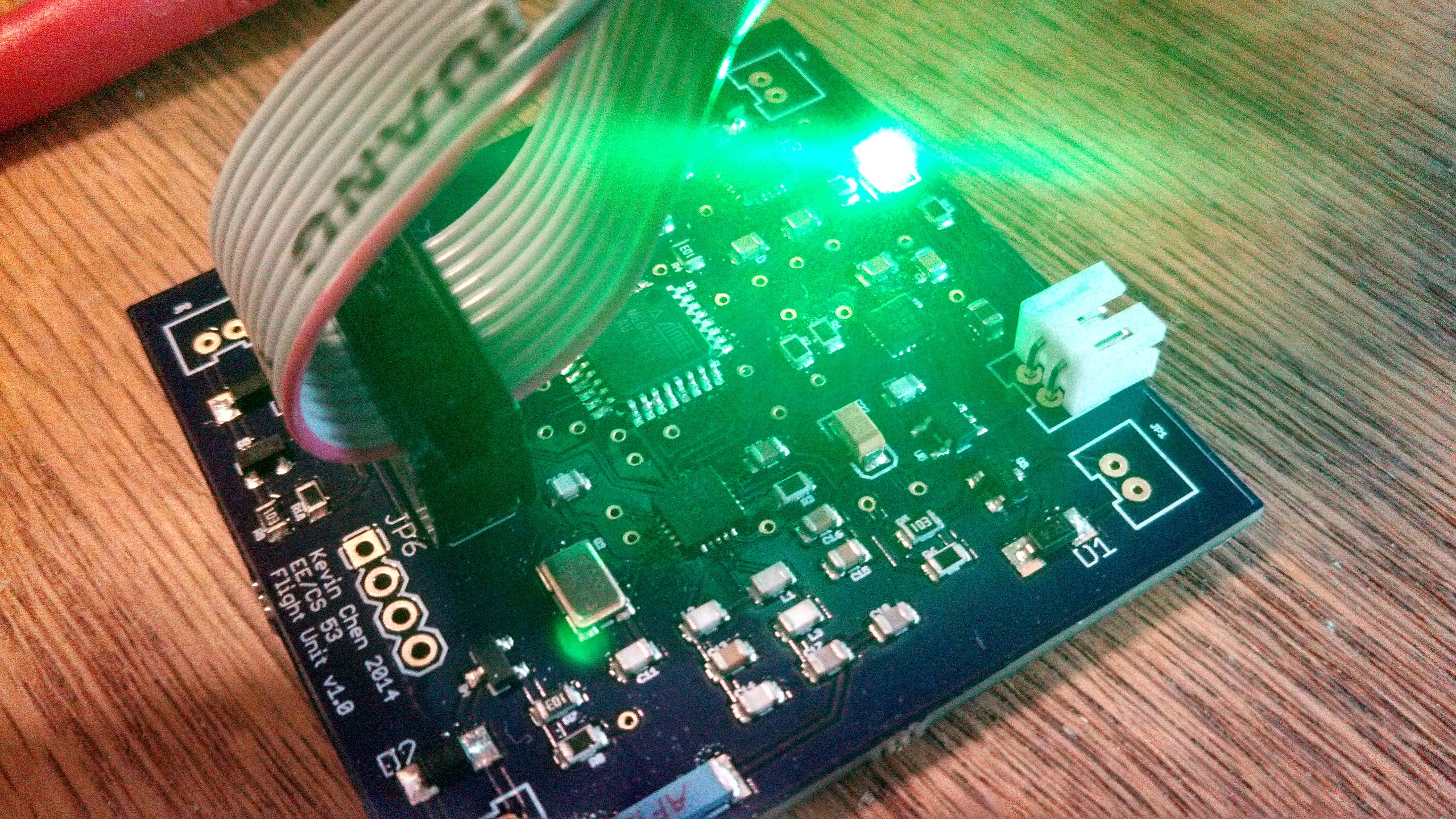
Software
The software for both the Flight Unit and Remote Unit was written in C and compiled using avr-gcc 4.3.3. A lot of the initial software work was the groudwork to read or communicate with the various components (e.g. setting up I2C or SPI registers). I unfortunately did not have the foresight to break out serial port pins; for the flight unit, early debugging involved measuring the voltage of a single pin that I could toggle at specific points in the code. This became a lot easier once I got the nRF chip working and was able to actually send and receive data.
PID Controllers
The quadcopter is controlled and balanced using a number of PID control loops. For the pitch and roll axes, the Flight Unit attempts to use both the accelerometer and gyroscope to maintain the quadcopter’s absolute angle at the controller set angle (0 for a stable hover), using 2 PID loops per axis. For the yaw axis, the Flight Unit cannot get any useful absolute angle information from the accelerometer; thus, it uses only 1 PID loop to maintain the quadcopter’s angular yaw rate at the controller set rate (0 for approximately no yaw).
 |
|---|
| The PID loops for the pitch/roll axes. |
 |
| The PID loop for the yaw axis. |
Filters
To estimate the rotation of the quadcopter along the pitch and roll axes, a complementary filter is used to combine the accelerometer angular data and the gyroscope angular rate data. In addition, because the raw accelerometer data is relatively noisy, the accelerometer angle is first filtered using an exponential moving average filter applied approximately every 10ms before it is fed into the complementary filter.
Communication Protocol
The Flight Unit and Remote Unit communicate using 5-byte packets. The following types of packets are used:
Flight Command Packet
This is sent by the Remote Unit to the Flight Unit to directly control the quadcopter in fight mode. It is sent approximately every 20ms:
| Byte # | Data |
|---|---|
| 0 | 100 |
| 1 | Yaw angular rate |
| 2 | Throttle level |
| 3 | Roll angle |
| 4 | Pitch angle |
PID Tune Command
This is sent by the Remote Unit to the Flight Unit to change the coefficients of the different PID loops that the Flight Unit uses to balance the quadcopter:
| Byte # | Data |
|---|---|
| 0 | (1 = pitch/roll stability) (2 = pitch/roll rate) (3 = yaw rate) (4 = alt rate - unused) |
| 1 | P coefficient |
| 2 | I coefficient |
| 3 | D coefficient |
| 4 | unused |
Calibrate Command
This is sent by the Remote Unit to the Flight Unit to make the Flight Unit zero the accelerometer and gyroscope (the process takes involves averaging 10 samples and using that as the zero level for both chips):
| Byte # | Data |
|---|---|
| 0 | 0 |
| 1 | unused |
| 2 | unused |
| 3 | unused |
| 4 | unused |
Flight Unit Status
The Flight Unit acknowledges each command packet from the Remote Unit with this status packet (using the built-in ack payload feature of the nRF24L01+ chip). Each status packet contains the following data:
0 Battery voltage - unused 1 Filtered pitch angle 2 Filtered roll angle 3 Filtered accelerometer x-axis angle 4 Altitude
| Byte # | Data |
|---|---|
| 0 | Battery voltage - unused |
| 1 | Filtered pitch angle |
| 2 | Filtered roll angle |
| 3 | Filtered accelerometer x-axis angle |
| 4 | Altitude |
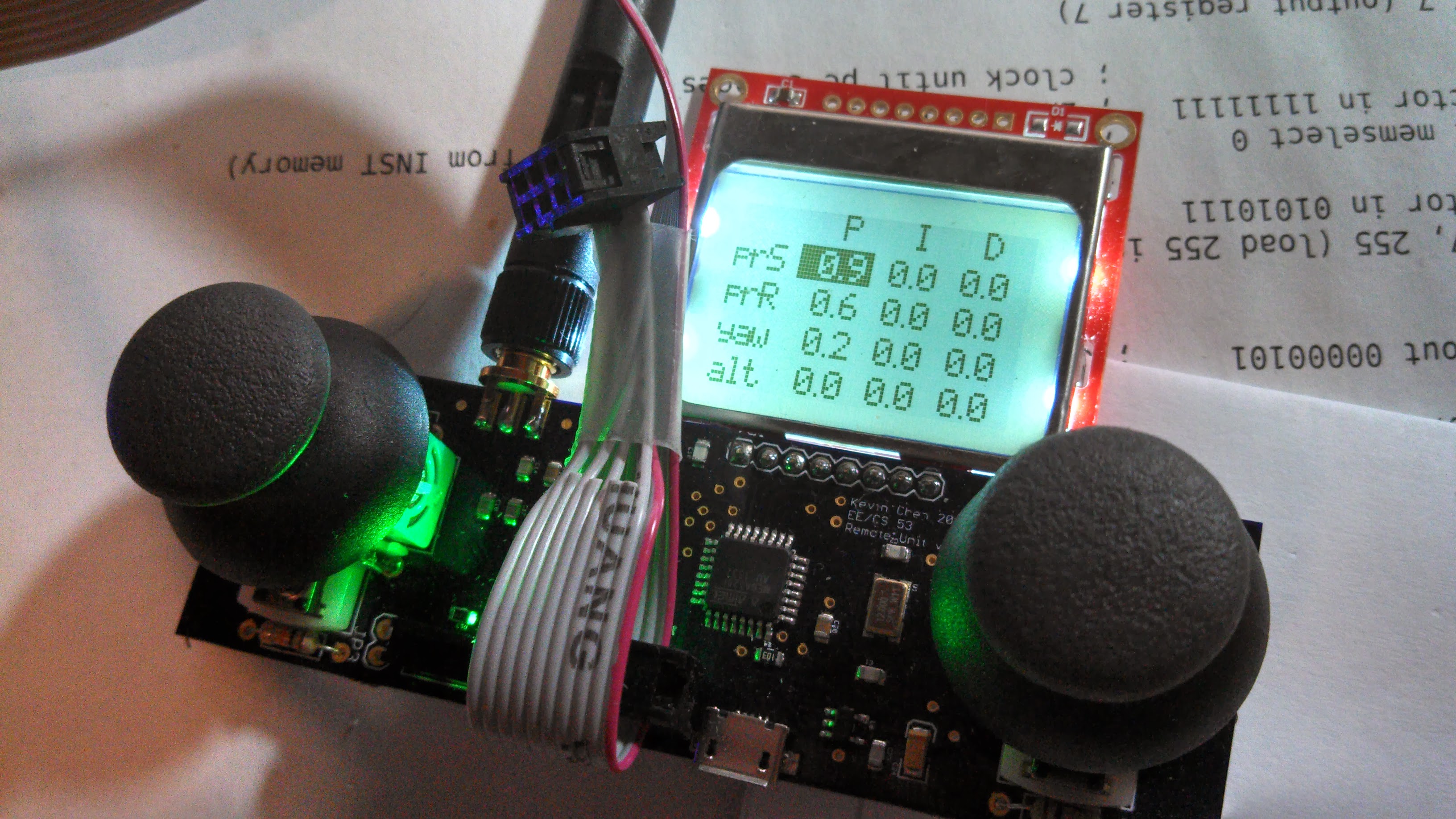
Remote Unit Interface
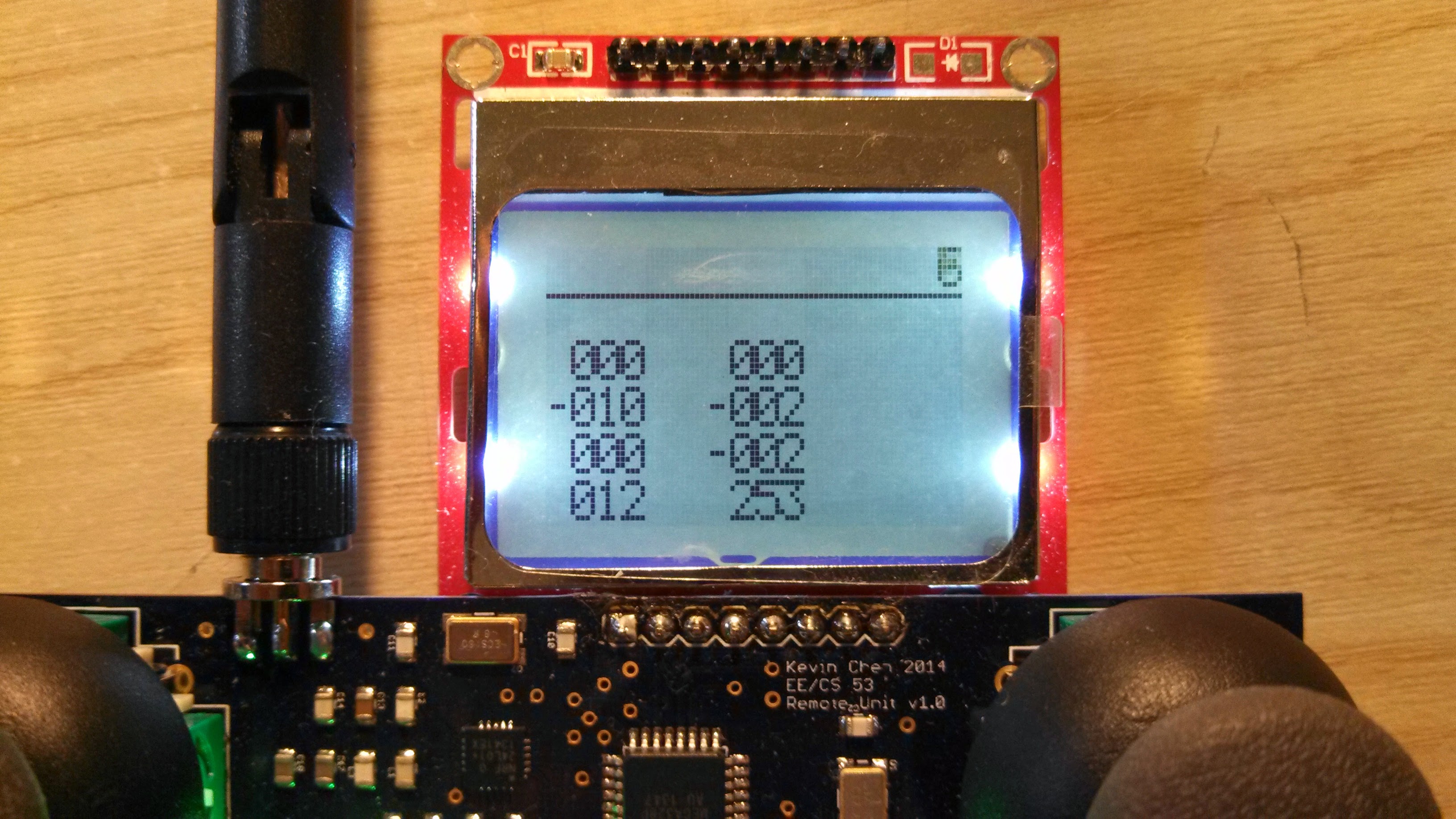
The remote can display a variety of data on its LCD. In the default flight mode, where the anlog sticks directly control the quadcopter, the following displays are available:
- Default (shows all status info in numeric form)
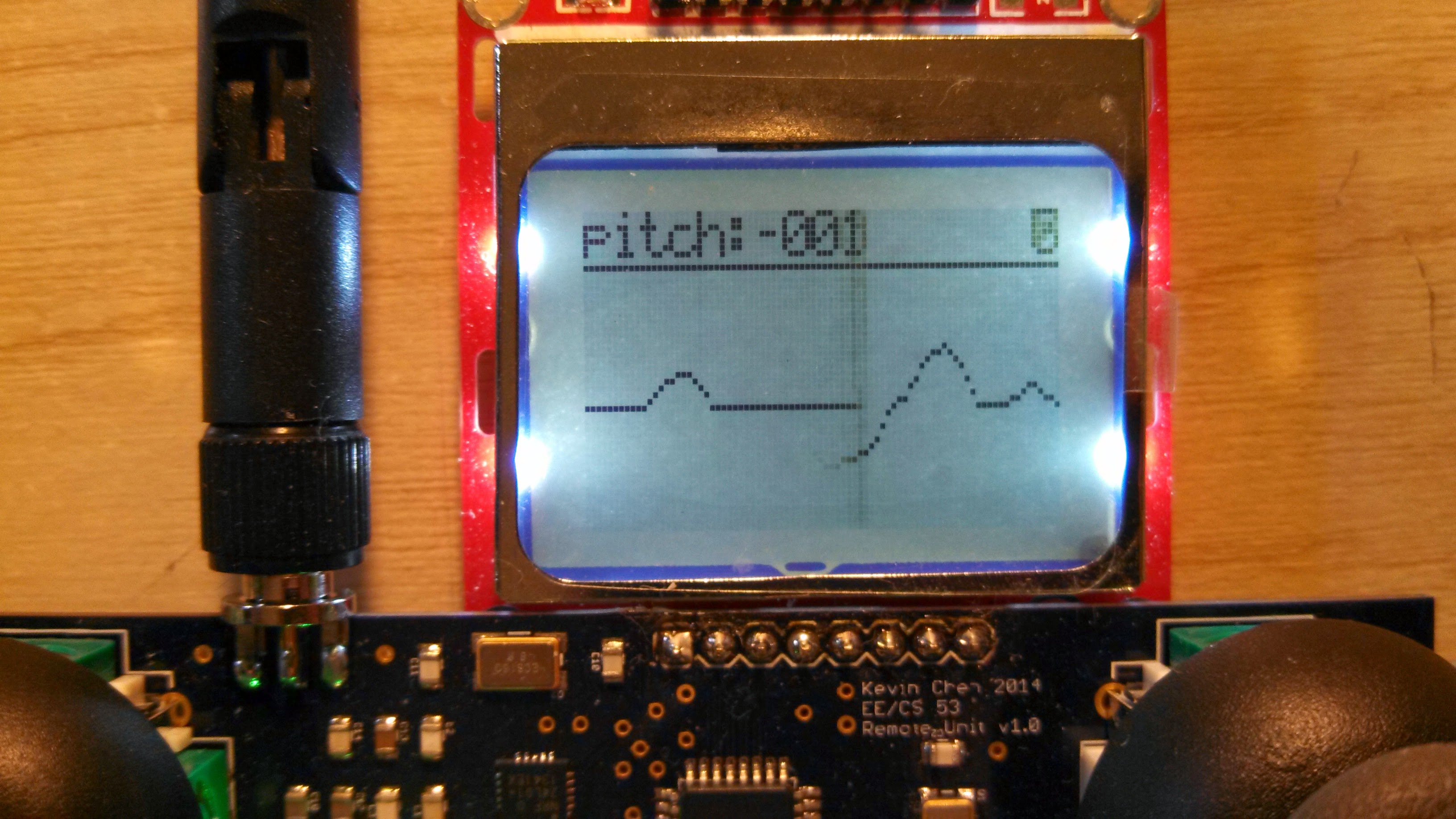
- Filtered pitch angle time series
- Filtered roll angle time series
- Accelerometer x-axis time series
- Attitude time series
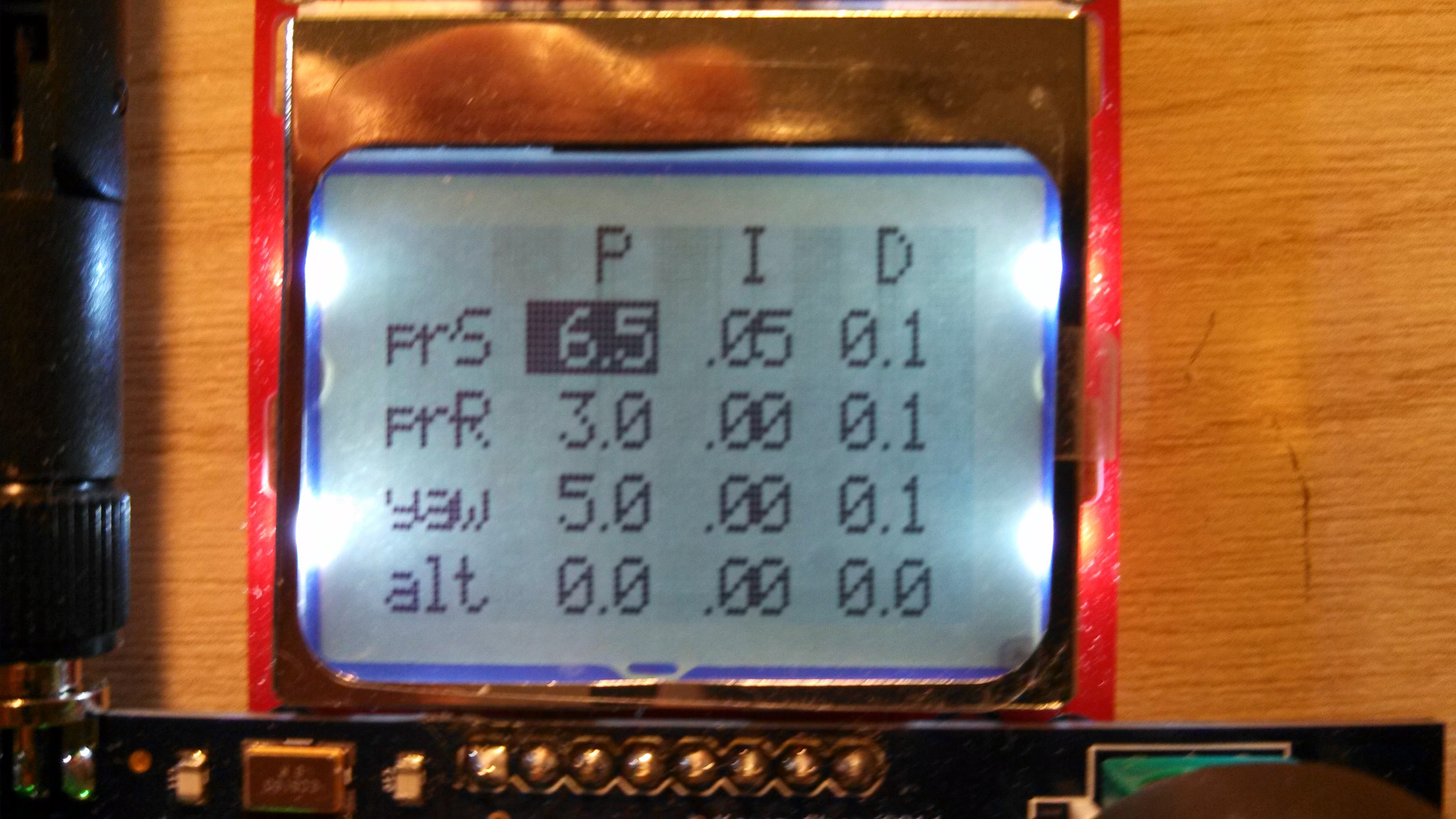
In the PID tuning mode, the display shows an editable interface of the PID coefficients of the flight unit.